Switch Vr I Qi
Max =V/R=100mA We can replace τ = L/R = RC to obtain an equivalent circuit C = L/R2=25e8F=25nF R=1K 10V i L=25mH An engineer wishes to replace the inductor with a capacitor giving the same time constant What is the value of C?.
Switch vr i qi. • Now we switch coordinates from xA;. V =Rv T≻0be the weighting matrices for the state and continuouscontrol input in subsystem v∈ M Each hybridcontrol sequence ψ∞ ={(ut,vt)} ∞ t=0 is associated with a quadratic performance index J∞ (z,ψ∞)= X∞ t=0 L(xt,ut,vt), (4) where xt is the closedloop trajectory controlled by ψ∞, with initial condition x 0 =z∈ Rn Our objective is to find the optimal hybridcontro. The NCV472 dual channel High Side Switch (HSS) with 250 mA per channel is designed for use in harsh automotive environments The device has a high peak input voltage tolerance and reverse input voltage, reverse bias, overcurrent and overtemperature protections The integrated current sense feature (adjustable by resistor connected to CSO pin for each channel) provides diagnosis.
PortalElectronics/Selected article/2 Joule's laws are a set of two laws concerning the heat produced by a current and the energy dependence of an ideal gas to that of pressure, volume, and temperature, respecetively Joule's first law, also known as the Joule effect, is a physical law expressing the relationship between the heat generated by the current flowing through a. 01/05/10 · The principle of operation of switched capacitor converters When the switch is in the left position, C1 charges to V1 The total charge on C1 is given by q1 = C1V1 When the switch moves to the right position, C1 discharges to V2. 4 Discharging capacitors qualitative 0 After switch s is closed Æ V C decreases Æ I C s I G Sciolla – MIT 8022 – Lecture 9 Before switch s is closed Difference in potential between C plates V No current circulating in the circuit (open) Difference in potential between capacitor plates will induce.
2R 1) I R = 0 2) I R = ε/(3R) I R ε C R3) IR= ε/(2R) 4) I R = ε/R S 1 S 2 KLR q 0 /C – IR = 0 Recall q is charge on capacitor after charging q 0 = εC (since charged w/ switch 2 open!) Physics 102 Lecture 7, Slide 11. IQ IIN Operating Current NonSwitching, FB = 3 V, SW = Open 22 38 mA Switch Characteristics Rds(on) Buck Switch Rds(on) ITEST = 0 mA 035 09 (DSBGA) Ω Buck Switch Rds(on) ITEST = 0 mA 045 1 (WSON12) UVLOGD Gate Drive UVLO VBST VSW Increasing 240 295 360 V VBST VSW Decreasing 2 UVLOGD Hysteresis 130 mV Softstart Pin VSS Pull. 2 The usefulness of electrical appliances eg in the home You should read about types of energy and energy stores first before studying this page See the notes Types of energy & stores examples compared and explained Appreciate that we often use electrical appliances because they transfer energy into other useful at the flick of a switch ie very convenient!.
17/01/13 · ABC transporters are a subset of nucleotide hydrolases that contain a signature motif, Qloop, and Hloop/switch region, in addition to, the Walker A motif/Ploop and Walker B motif commonly found in a number of ATP and GTPbinding and hydrolyzing proteins Links?. A resistor R in series connected by switch s What happens when switch s is closed?. Circuit symbol for an open switch, this breaks a circuit so that it is 'off', and current can't flow circuit symbol for a two way switch , in which one route is 'open' and the other 'closed' , , , circuit symbols for 1, 2, 3 or many cells wired in series (>1 cell often referred to as a ' battery '), the short stubby vertical line is the negative pole and the long thin vertical line is the.
25nF 11 Example 2#7 RC Circuit Describe the current which flows to point A when the switch. V R maximum allowable DC reverse voltage τ carrier lifetime Q = I F χ τ (coulombs) W = Iregion width switch may be designed using either a single series or shunt connected PIN diode as shown in Figure 5 The series connected diode switch is commonly used when minimum insertion loss is required over a broad frequency range This design is also eas ier to physically realize. CURRENT, POTENTIAL DIFFERENCE AND RESISTANCE Current is the rate of flow of charge measured in Ampere One Ampere is the current flowing when one coulomb of charge flows through one second Resistance is the obstruction to the flow of.
Here, Q 0, V 0 and I 0 refer to the charge, voltage and current of the capacitor in the instant after the switch is thrown The time t is the characteristic time of the decay, t = RCWhen confronted with an RC problem, the best strategy is the following Decide what the charge across the capacitor was just before the switch was thrown Since the charge can not change instantly, this is the. 01/12/17 · The switch proposed in this paper manages microfluidic frames consisting of a train of (N (Δ V = R I) and the Hagen Referring to Fig 6, the equivalent downstream resistance seen after each junction i of the electrical network R O 1, e q (i) can be recursively expressed as follows (21) R O 1, e q (i) = R O 1 (n), for i = n;. Here, Q 0, V 0 and I 0 refer to the charge, voltage and current of the capacitor in the instant after the switch is thrown The time t is the characteristic time of the decay, t = RCWhen confronted with an RC problem, the best strategy is the following Decide what the charge across the capacitor was just before the switch was thrown.
HEXFET Power MOSFET Notes through are on page 8 Applications • Control MOSFET for high frequency buck converters PQFN 33 X 33 mm Orderable Part Number Form Quantity IRFHM34PBF PQFN 33mm x 33mm Tape and Reel 4000 IRFHM34TRPBF. • Capacitor uncharged, switch is moved to position “a” I 13 Physics 212 Lecture 11, Slide 3 Checkpoint 1a Checkpoint 1b & Close S1, V 1 = voltage across C immediately after V 2 = voltage across C a long time after D) V A) V 1 = V V 2 = V B) V 1 = 0 V 2 = V C) V 1 = 0 V 2 = 0 1 = V V = 0 Immediately after the switch S 1 is closed Q = 0 V = Q/C V 1 = 0 After the switch S 1 has been. 26/05/19 · Let I be the current flowing in the circuit and V R (= IR) the potential difference across resistance At time t = 0, it is connected to an inductor through a switch S At time t = 0, switch S is closed Refer figure (b) When the switch is closed, the capacitor starts discharging Let at time t charge on the capacitor is q (< q 0) and since, it is further decreasing there is a current i in.
21 The switch in Figure P3221 is open for t < 0 and is then 0 Assume R = 400 Q, L thrown closed at time t 100 H, and = 100 V Find (a) the current in the induc tor and (b) the current in the switch as functions of time thereafter 211 Figure P3221 Problems 21, 22, and 60 19 In the circuit shown in Figure P3216, let L = 700 H, R 900 Q, and = 1 V What is the selfinduced emf00. Meraki MS Switches are the industry's only switches featuring integrated Layer 7 application and client fingerprinting and analysis Hundreds of applications. V r e s i s t o r = ε V_{resistor} = \varepsilon V r e s i s t o r = ε i = V r e s i s t o r R = ε R i = \frac{V_{resistor}}{R} = \frac{\varepsilon}{R} i = R V r e s i s t o r = R ε Time approaches infinity After a long time, the capacitor is allowed to reach its maximum charge Since no current flows, the resistor uses no voltage i = 0.
V R C Q Q I 0 0 W Lecture 11 –5/18 The switch S is initially at position afor a long time It is then switched to position b Describe what happens to the light bulb as a function of time after the switch is flipped from ato b Quiz Question 4 a) The light bulb goes on but goes off immediately b) The light bulb goes off and stays off c) The light bulb goes on but its brightness. = f = 0 Thus, in these generalized coordinates, the constraint forces have disappeared We may restrict to the coordinates qa and use the original Lagrangian L Note that in such an. The PHYRE automatic fold recognition server for predicting the structure and/or function of your protein sequence.
Attached to a resistor R with a switch 0 0 Q Q CV VC =⇒= Close the switch at time t = 0 , so current I starts to flow The charged capacitor is acting like a battery it produces a voltage difference across the resistor which drives the current through the resistor At t = 0, 0 0 V I R = dQ I dt =− (– sign because Q is decreasing). Contacts at 40A View structure with Cn3D Citation PMID Download Cn3D for Viewing 3D Structure Scroll to Sequence Alignment Display Sequence Alignment include consensus sequence?. 90 V R4 R1 R R2 3 I Lecture multiple choice (43 pts) ANSWER ON SCANTRON SHEET For questions 13, four resistors are connected to an ideal battery as shown After the switch is closed, the system quickly reaches a steadystate condition so that all currents are constant Use the following values 1 (3 pts) Which choice best represents the.
It may also use one or more voltage amplification devices like transistors to boost voltage during sags Because of the non. What About Switched Capacitor Converters?. I) Drift velocity is the average velocity of the free electrons in the conductor with which they get drifted towards the positive end of the conductor under the influence of an external electric fieldii) Free electrons are in continuous random motion They undergo changethey undergo change in direction at each collision and the thermal velocities are randomly distributef in all directions.
Grad Students Michael Seeman, Vincent Ng, and HanhPhuc Le Profs Seth Sanders and Elad Alon EECS Department, UC Berkeley Switched Capacitor Power Converters • Only switches and capacitors • Simple low freq model as an ideal transformer with Thevenin impedance – neglects freq dependent loss and leakage – Would model. Switch open Switch closed I B1o 0 V B1o 0V I B1c 5V 07V R B I B1c = 108 mA V B2o 07V assume Q1 is in saturation V C1c 02V I B2o V CC 07V R 2 I B2o = 286 mA I C1c V CC V C1c R 2 I C1c = 296 mA I R2o I B2o I R2o = 286 mA β1I B1c = 86 mA IC1 is controlled by R2 I C2o β2IB2o I C2o = 715 mA V B2c V C1c V B2c = 02 V V C2o V CC R CI C2o V C2o =. Q I r F A V Fdi /dt di F /dt A/µs A V µC A/µs A/µs t rr ns t fr Z thJC A/µs µs 005 01 02 03 05 D=07 005 DSEI 2x Single Pulse I F =0A I F =100A I F = 50A T VJ = 100°C V R = 600V T = 100°C I F = 100A Fig 3 Peak reverse current I RM versus di F /dt Fig 2 Reverse recovery charge Q r versus di F /dt Fig 1 Forward.
25/02/02 · Switchedmode power supplies usually include a voltage regulator as part of the circuit Voltage regulation is based on a different principle than filtering it relies on the peak inverse voltage of a diode or series of diodes to set a maximum output voltage;. Lem to switched linear systems (SLS), which will be referred to as the DiscreteTime Switched LQR (DSLQR) Problem The goal is to find both the continuouscontrol and switchingcontrol strategies to minimize a quadratic cost functional over an infinite time horizon The problem is expected to play a fundamental role in the study of switched and hybrid systems as the classical LQR. Z S p V R o n s 3 o r e 0 U d J D L 4 New Listing Johnson Evinrude OMC Trim/Tilt Switch HP Used PreOwned C $42 Top Rated Seller Top Rated Seller or Best Offer from United States Free returns S p 9 o G n s o 1 r 8 e 3 D d A O V 2 5 New Listing JOHNSON EVINRUDE CONTROL BOX TRIM TILT SWITCH & COVER PLATE.
The voltage characteristics of the circuit remains the same!. V R IR (2) In this laboratory you will measure the voltage across the resistor and capacitor in two Make sure that the capacitor is initially discharged by placing the switch in the discharge position, with R set to zero Then set the resistance, using the decade box, to a suitable value (compute an approximate value of R to give τ ~ 05 sec) Note down the value of resistance in table 1. For Switched Linear Systems Wei Zhang, Alessandro Abate, Michael P Vitus and Jianghai Hu Abstract—In this paper, we prove that a discretetime switched linear system is exponentially stabilizable if and only if there exists a stationary hybridcontrol law that consists of a homogeneous switchingcontrol law and a piecewiselinear continuouscontrol law under which the closed.
V Re q I V=V1V2 Equivalent circuit 3 Resistors in parallel When resistors are arranged in parallel, the current has multiple paths to take Nevertheless, the currents of different paths must add to equal the total current entering the parallel combination, ie, I1 I2 = I At the same time, each resistor is connected completely across the voltage supply So, the potential difference across. The work on EMF and internal resistance draws on ideas about voltage, current and charge that were discussed in previous sections The idea of EMF (electromotive force) has already been introduced but may well need reinforcement, along with the definition of the volt, and there is a lot to be gained by beginning this work with a general discussion of energy transfers within electric. When the switch is in position A, the capacitor C gains a charge Q 0 so that the pd across the capacitor V 0 equals the battery emf When the switch is moved to position B, the discharge process begins Suppose that at a time t, the charge has fallen to Q, the pd is V and there is a current I flowing as shown At this moment I = V R (equation 1).
02/01/21 · Nothing happens while the switch is open (dashed line) When the switch \label{eq631} V_R=IR,\ where \(I\) is current and \(R\) is a positive constant, the resistance of the resistor The voltage drop across the induction coil is given by \\label{eq632} V_I=L{dI\over dt}=LI',\ where \(L\) is a positive constant, the inductance of the coil A capacitor stores. Draw a circuit diagram with a battery, bulb and a switch How will you measure the current and potential Difference of the Circuit ?. , continuing to use the Lagrangian L0 The Euler{Lagrange equations are simply d dt @L @q_a @L @q i = @ @qa f = 0;.
26/08/ · Let us assume above, that the capacitor, C is fully “discharged” and the switch (S) is fully open These are the initial conditions of the circuit, then t = 0, i = 0 and q = 0 When the switch is closed the time begins at t = 0 and current begins to flow into the capacitor via the resistor Since the initial voltage across the capacitor is zero, ( Vc = 0 ) at t = 0 the capacitor appears to. After switch 1 has been closed for a long time, it is opened and switch 2 is closed What is the current through the right resistor just after switch 2 is closed?. Source cd Taxonomy cellular organisms PubMed 11 links Protein Representatives Specific.
Switch Dimensions see outlinespdf Pulse test ① Pulse Q IRM r I F A VFdi F/dt di F /dt A/m s A V nC A/m s A/m s t rr ns tfr A/m s µs DSEP 6006A ZthJC I F =1A I F = 60A I F = 30A T VJ = 100 °C V R = 300V T VJ = 100 °C I F = 60A Fig 3 Peak reverse current I RM versus di F /dt Fig 2 Reverse recovery charge Q r versus di F /dt Fig 1 Forward current I F versus V F T VJ = 100 °C. 17/01/13 · GTP/Mg2 Switch I region Switch II G1 box G2 box Feature 1 GTP/Mg2 binding site chemical binding site Evidence Structure 2QAG Human Septin binds GTP;. 2 wwwirfcom S D G Static @ T J = 25°C (unless otherwise specified) Parameter Min Typ Max Units BV DSS DraintoSource Breakdown Voltage 30 ––– ––– V DSS/∆T J Breakdown Voltage Temp Coefficient ––– 0021 ––– mV/°C R DS(on) Static DraintoSource OnResistance ––– 50 63 mΩ ––– 62 78 VGS(th) Gate Threshold Voltage 135 ––– 225 V.
V BB 5V R B 4kΩ I B1= ?. 08/05/11 · The power loss is given by I ^2 R where I is the current and R is the resitance I know why these variables are in this equation V = I R P = I V therefore, P = I² R What I don't understand is the practical explanations for this Why are there two current variables?. This causes the output to switch into a biased mode after a time constant is elapsed The time constant is determined by the external capacitor Filtering avoids ageing and temperature influence from Schmitttrigger input and eliminates device and magnetic offset The TLEU can be exploited to detect toothed wheel rotation in a rough environment Jolts against the toothed.
Atelier Arland Series Deluxe Pack is available now for the first time on the PS4 and Nintendo Switch™ The game will also be released on Windows PC via Stea. The switched linear system (1) is asymptotically stable under an arbitrary switching rule, for any two consecutive events at t k and t k1, there exists a minimum duration ˝>0, such that t k t k1 ˝, for all k2N 3 Eventtriggered Control Algorithm 31 Algorithm Description A su cient condition for the stability of a switched linear system under arbitrary switching is the existence of a.

Nintendo Unveils The Full Set Of Accessories In The Nintendo Labo Vr Kit

Solved In The Circuit Given Below R 50 Q The Switch In Chegg Com
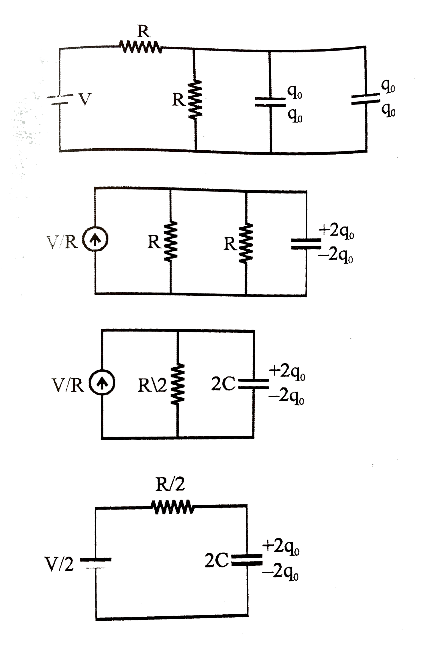
Initially The Switch Is Open For A Long Time Now The Switch Is Cl
Switch Vr I Qi のギャラリー

Pdf A Mems T R Switch Embedded In Cmut Structure For Ultrasound Imaging Frontends

Linbo3

Solved A Series Rl Circuit With R 33 Q And L 12 H Has Chegg Com

Chapter 25 Electric Circuits Voltage And Current Series
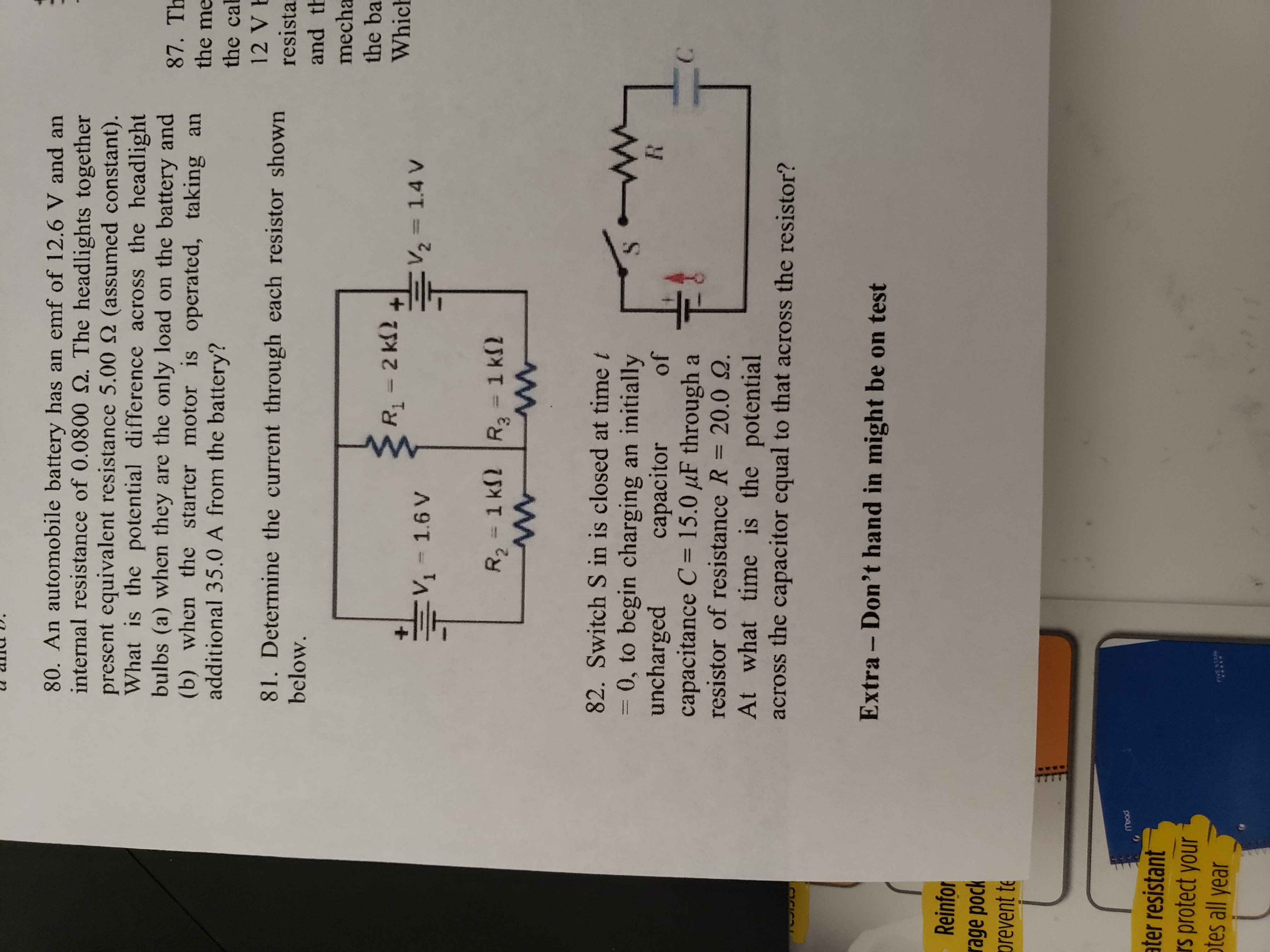
Answered Switch S In Is Closed At Time T 30 Bartleby

The Nintendo Switch Has A Hidden Vr Mode Hypebeast

Nintendo S Latest Labo Kit Explores Simple Vr Gaming Experiences

Solved What Is The Charge Q Accumulated On The Capacitor Chegg Com
Vizzard Cnc Switch Aluminium Alloy Switches 1 25mm Vr Pack Of 1 16 A One Way Electrical Switch Price In India Buy Vizzard Cnc Switch Aluminium Alloy Switches 1 25mm Vr
Two Loop Rc Circuit 1
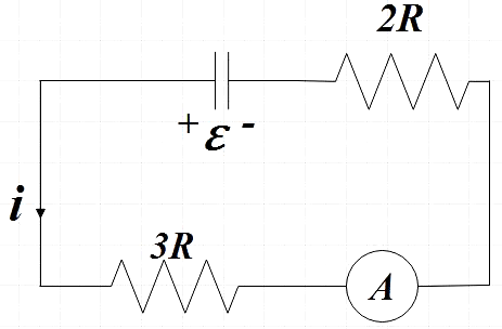
Switch S1 Is Closed For A Long Time While S2 Remains Class 12 Physics Jee Main

Patent Hints At Nintendo Switch Vr Headset Hypebeast

狼与辛香料vr 2 Switch 版发 综合讨论 Taptap 社区

Consider A Series Rc Circuit For Which R 1 0 Mw C 5 0 µf And E 30 V As In The Figure Youtube
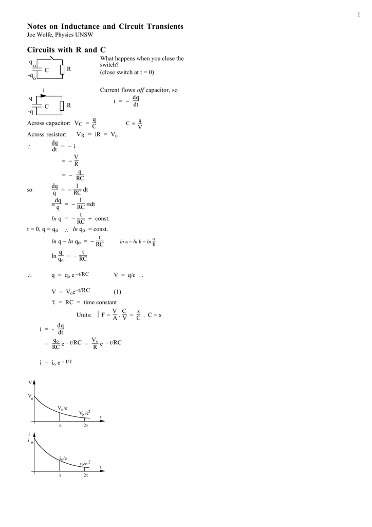
Transients And Inductance Notes

In Series Rl Circuit Switch Is Closed At T 0 The Charge Which Passes Through The Battery In One Time Constant Is M
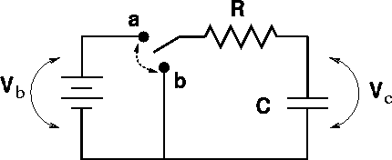
Rc Circuits

Solved For The Circuit Shown Below E 10 V R 10 Q An Chegg Com

Nintendo Labo Toy Con 04 Vr Kit For Nintendo Switch Shop4ie Com

A Electrical Analog Of Rgat1 The Switch Gaba Is Open In Absence Download Scientific Diagram

Resistors In Series And Parallel Physics

Original New 100 Tortoise Key Digital Accessories Touch Switch Wtcm V T R Dip 3 5 4 7mm Switches Aliexpress

Nintendo Switch V2 And Labo Bundle With Games Video Gaming Video Game Consoles Nintendo On Carousell
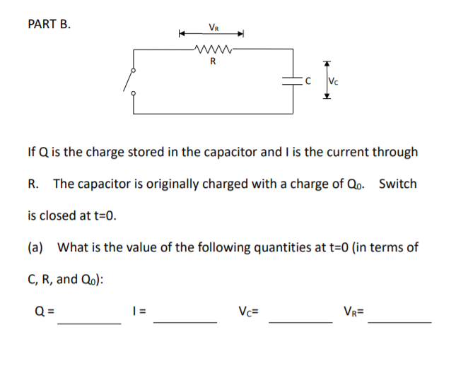
Part B Vr R If Q Is The Charge Stored In The Chegg Com

Initially The Switch Is Open For A Long Time Now The Switch Is Cl

Nintendo Switch Vr Teased In System Code Game Rant
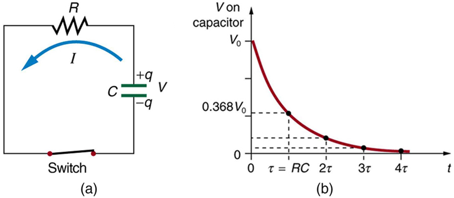
Dc Circuits Containing Resistors And Capacitors Physics
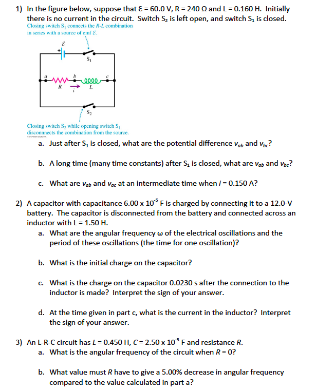
Solved In The Figure Below Suppose That 8 60 0 V R Chegg Com

How This Gamer Turned His Nintendo Switch Into A Vr Headset Vrscout

In The Given Circuit The Capacitor C May Be Charged Through Resistance R By A Battery V By Closing Switch S1 Also When S1 Is Opened And S2 Is Closed The Capacitor

P 8 4 3 Cardiac Pacemakers Are Used By People To Maintain Regular Heart Rhythm When They Have A Damaged Heart The Circuit Of A Pacemaker Can Be Represented As Shown In Figure P 8 4 3 The Resistance Of The Wires R Can Be Neglected Since R 1 Mw
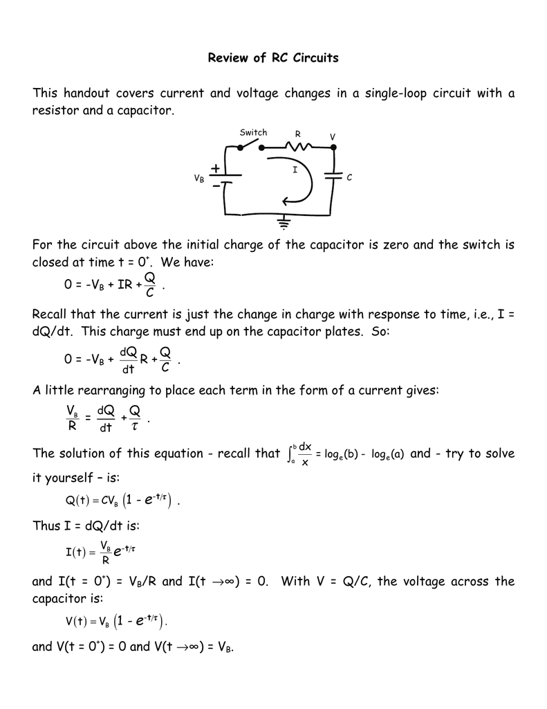
Document

Consider A Series Rc Circuit As In The Figure Below For Which R 1 00 Mw C 5 00 µf And E 30 0 Youtube

Buy Steelseries Arctis 3 All Platform Gaming Headset For Pc Playstation 4 Xbox One Nintendo Switch Vr Android And Ios Black Toys R Us

Nintendo Switch Games Receive Vr Update Hypebeast

Buy The Elder Scrolls V Skyrim Nintendo Switch Toys R Us

Current Electricity Q Kindly Explain Am E 0 V Switch O N2 3300 A Az In Physics Current Electricity Meritnation Com

Nintendo Announces Labo Vr Kit For Switch
Nintendo Switch Game Icon Customizer Simplify The Method Of Changing Game Icons Page 4 Q Bec Com The Independent Video Game Community

In The Circuit Shown In Figure C1 C2 C And Capacitor C1 Is Having Initial Charge Q The Switch Is Closed At T 0 Find The Heat Loss

Nintendo Labo Toy Con 04 Vr Kit Expansion Set 1 For Nintendo Switch Shop4ca Com
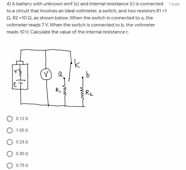
Answered 4 A Battery With Unknown Emf E And Bartleby
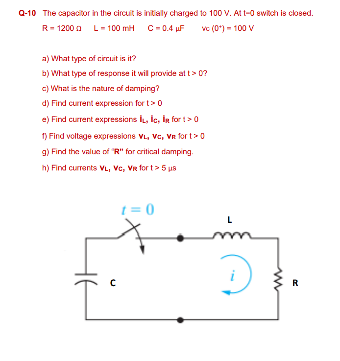
Solved Q 10 The Capacitor In The Circuit Is Initially Cha Chegg Com

Switch Modders Fire Up Test Vr Mode Screen

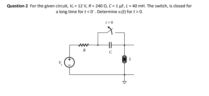
Answered Question 2 For The Given Circuit Vk Bartleby

Vuforia Ar Vr Sample With Google Cardboard Sdk I Cannot Switch From Augmented Reality To Virtual Reality Game Development Stack Exchange
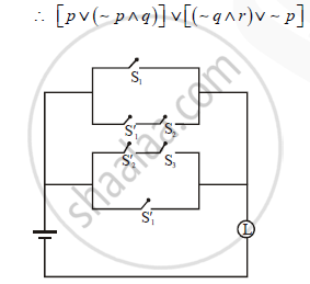
Construct The Switching Circuit For The Following Statement P V P Q V Q R V P Mathematics And Statistics Shaalaa Com
If 3 Bulbs P Q And R Are Connected As Shown In Figure Sarthaks Econnect Largest Online Education Community
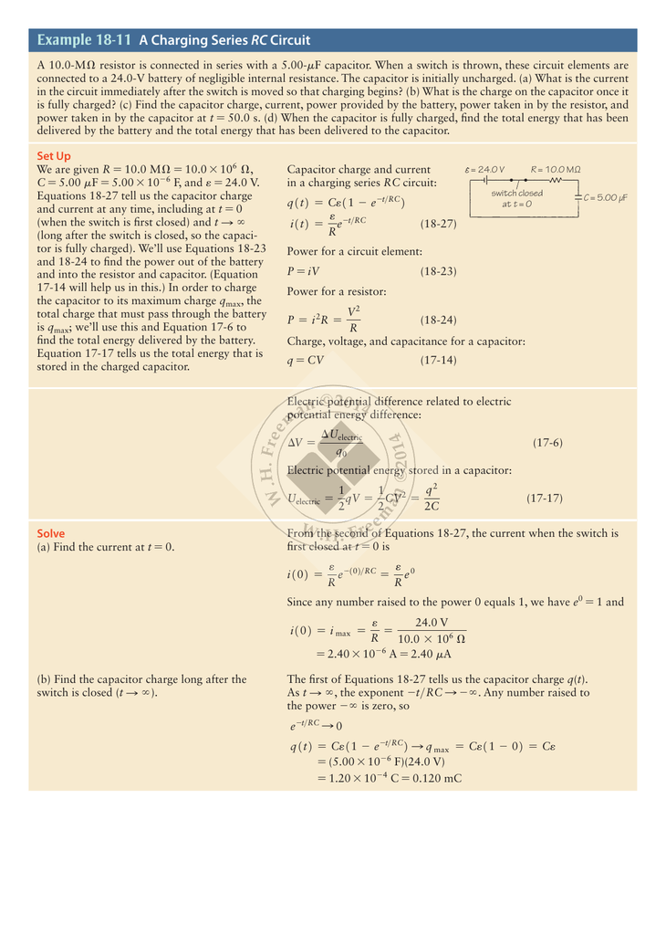
Example 18 11 A Charging Series Rc Circuit

Physics 212 Lecture 19 Lc And Rlc Circuits

Steelseries Arctis 3 19 Edition All Platform Gaming Headset For Pc Playstation 4 Xbox One Nintendo Switch Vr Mak Services

C Program To Check Vowel Or Consonant Using Switch Case Codeforcoding

Nintendo Please Bring Pokemon Snap To Labo Vr And These Other Games Too

Nintendo Labo Toy Con 04 Vr Kit Expansion Set 2 For Nintendo Switch 365games Co Uk

Switch From Vr To Ar With Powerful Wireless Sulon Q Headset

Tutorial Questions Oscillator Q 1 With The Aid

The Reviews Are In The Elder Scrolls V Skyrim Nintendo Switch Switch
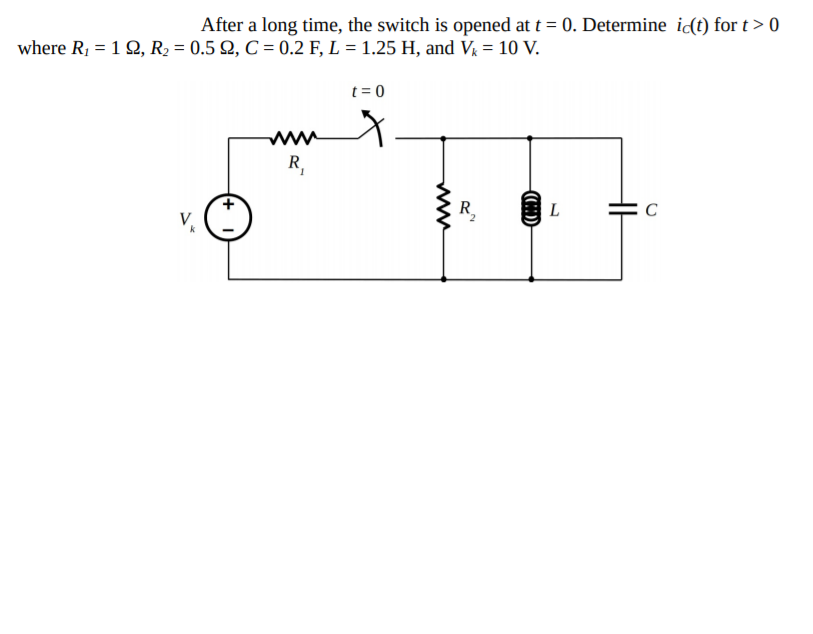
Answered After A Long Time The Switch Is Opened Bartleby
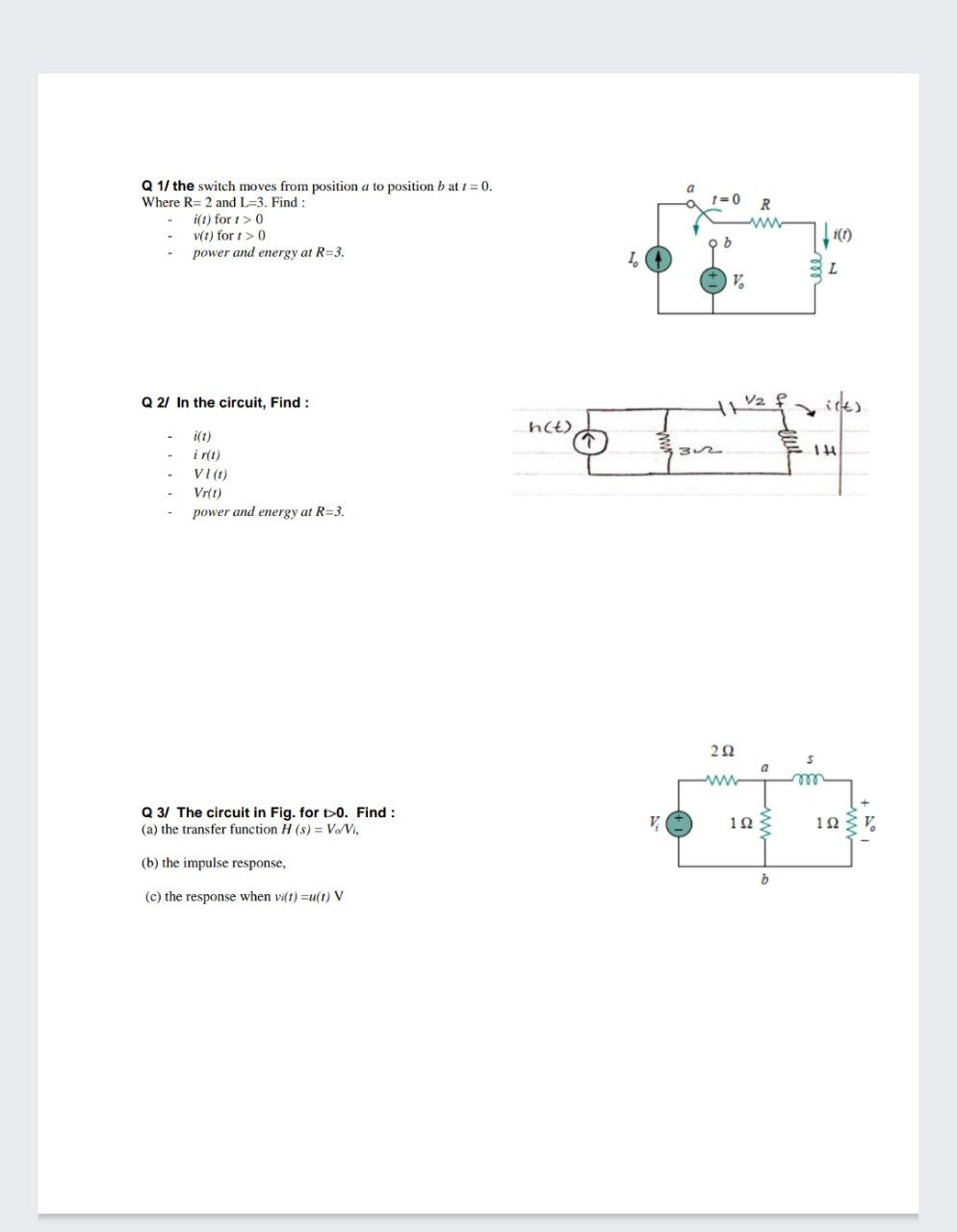
Answered Q 1 The Switch Moves From Position A Bartleby

How To Switch From Vr To Standard Mode During Open Level Ue4 Answerhub
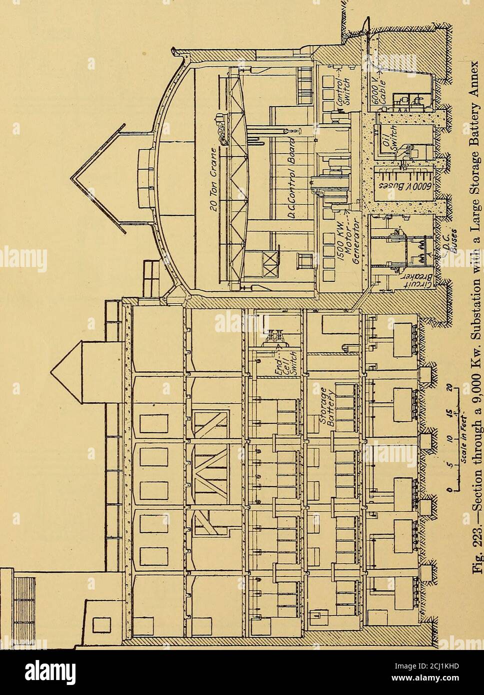
American Hydroelectric Practice A Compilation Of Useful Data And Information On The Design Construction And Operation Of Hydroelectric Systems From The Penstocks To Distribution Lines 40 To 71 Q
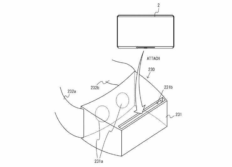
Nintendo Studying Possible Switch Vr Support Game Rant

Nintendo S Switch Vr Patent Filing Looks Like A Bad Joke
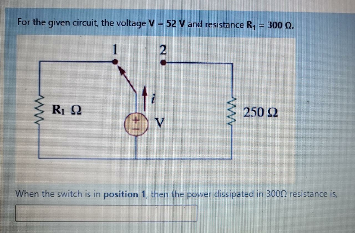
Answered For The Given Circuit The Voltage V Bartleby
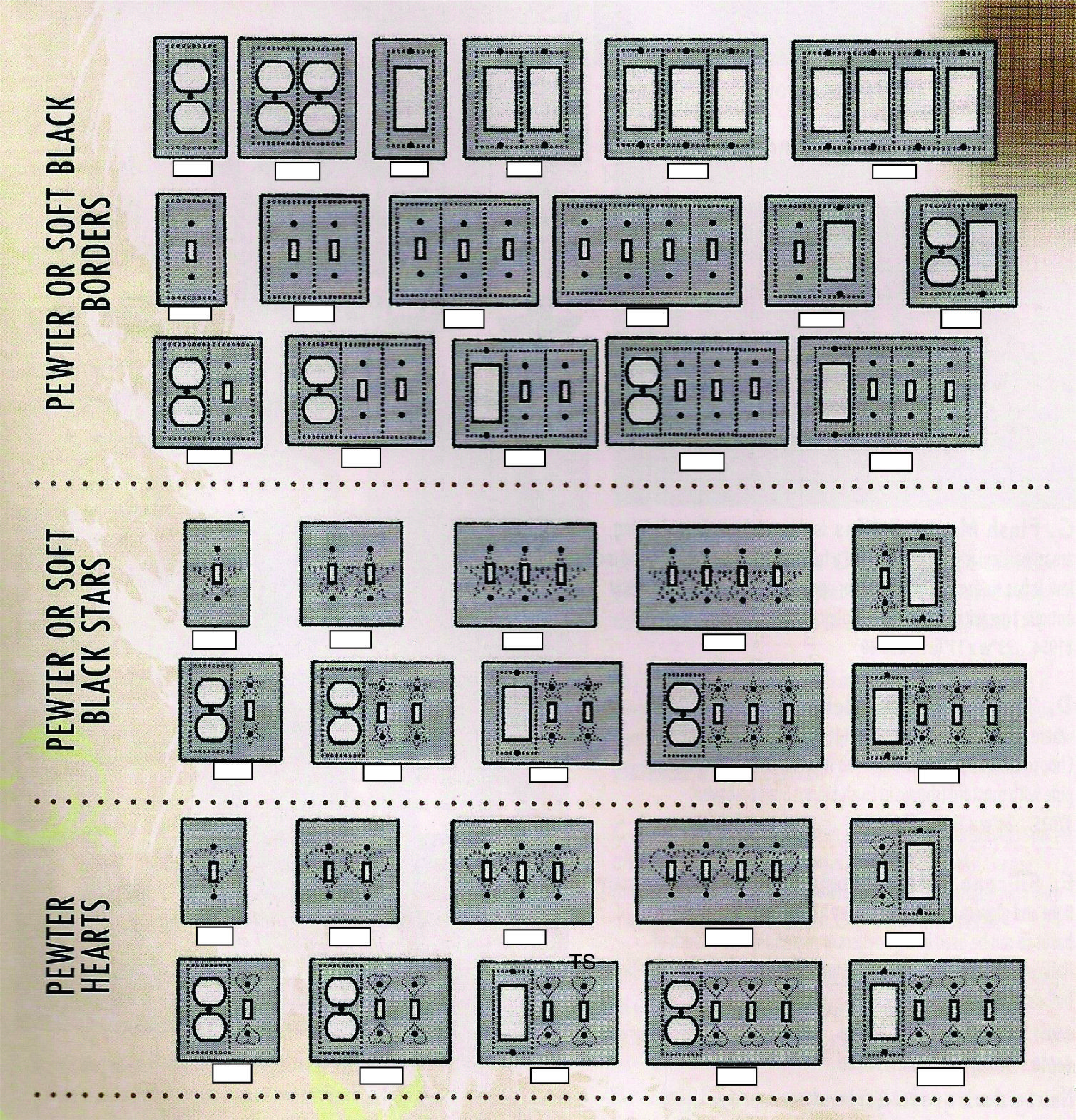
Pewter Heart Design Switch Plates
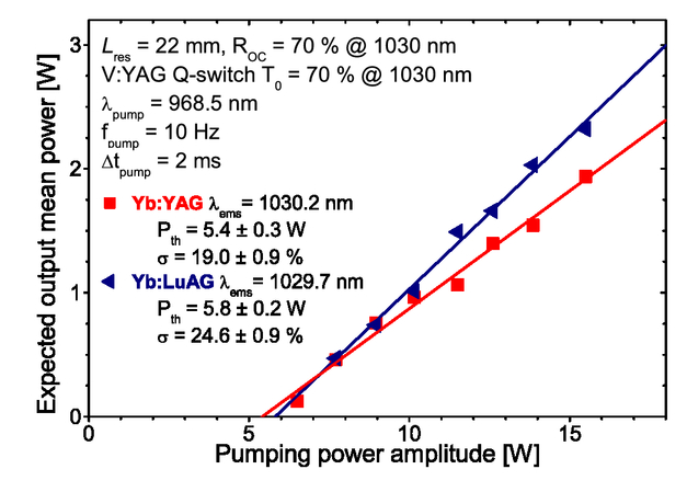
Diode Pumped Yb Lasers Q Switched By V Yag Saturable Absorber

A Point Charge Q Is Placed At A Distance X From The Centre Of A Conducting Sphere Of Youtube
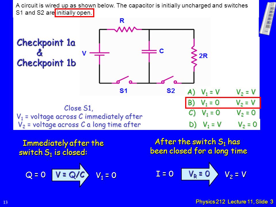
Physics 212 Lecture 11 Rc Circuits Change In Schedule Ppt Video Online Download

Pdf The Q Switching Instability In Passively Mode Locked Lasers
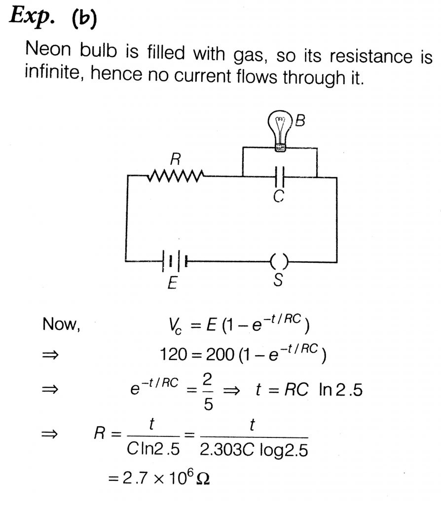
A Resistor R And 2 M F Capacitor In Series Is Connected Through A Switch To 0 V Direct Supply A Cross The Capacitor Is A Neon Bulb That Lights Up At 1 V
Sulon Q Vr Ar Headset Features Photos

At T0 The Switch S Is Closed See How To Solve It At Qanda

Amazon Com Vr Headset Compatible With Nintendo Switch Oivo 3d Vr Virtual Reality Glasses Labo Goggles Headset For Nintendo Switch Electronics

New Cisco C4kx Fan R Front To Back Switch Cooling Fan Module For Catalyst 4500 X
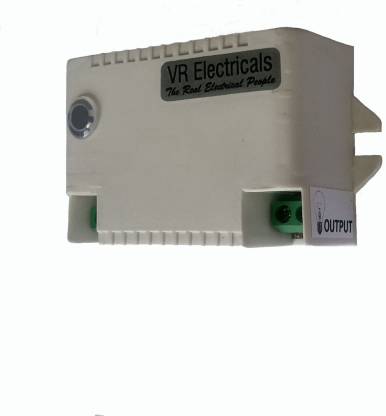
Vr Electricals Automatic Night Switch 5 A Motion Sensor Electrical Switch Price In India Buy Vr Electricals Automatic Night Switch 5 A Motion Sensor Electrical Switch Online At Flipkart Com
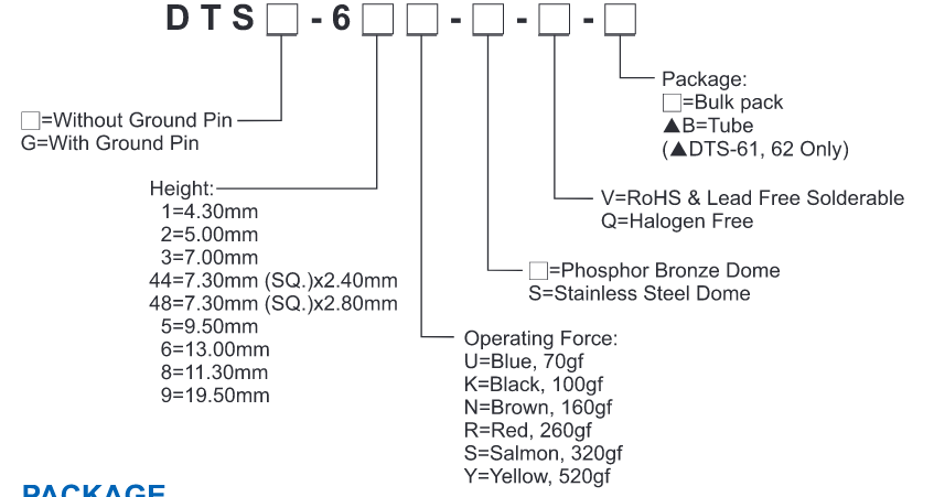
Diptronics Dts 62r V Small Switch Very Big And Very Cheap Oemsecrets Com

Nintendo Labo Toy Con 04 Vr Kit Starter Set With Blaster For Nintendo Switch Shop4malaysia Com
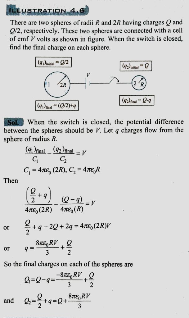
There Are Two Spheres Of Radii R And 2r Having Charges Q And Q 2 Respectively These Two Spheres Are Connected With A Cell Of Emf V Volts As Show In When The
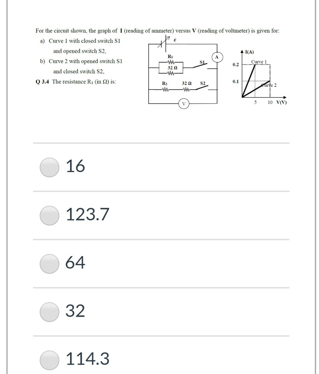
Answered For The Circuit Shown The Graph Of I Bartleby
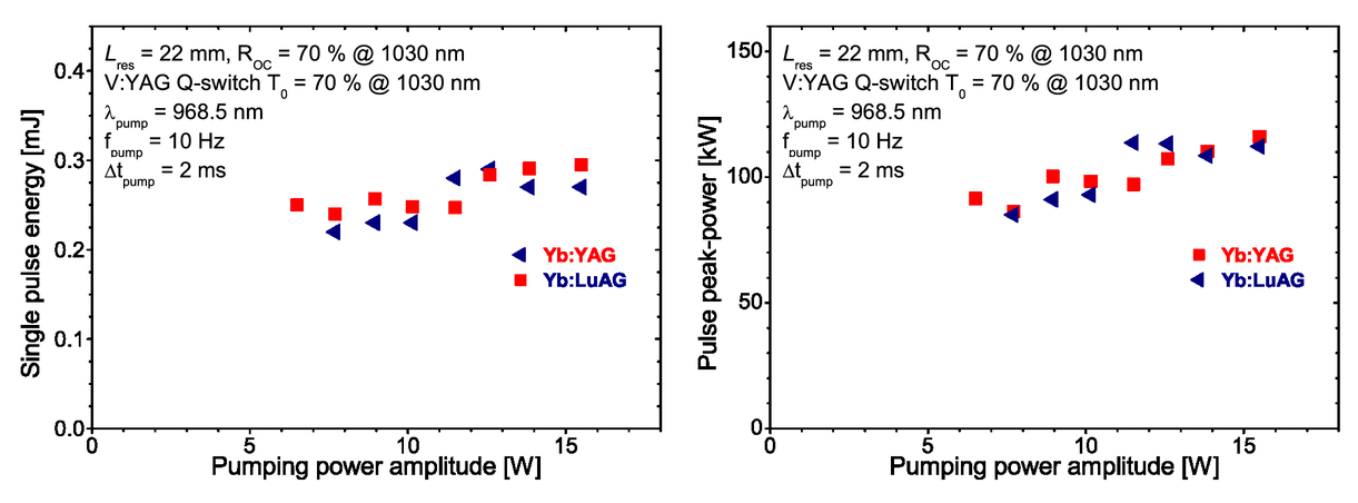
Diode Pumped Yb Lasers Q Switched By V Yag Saturable Absorber
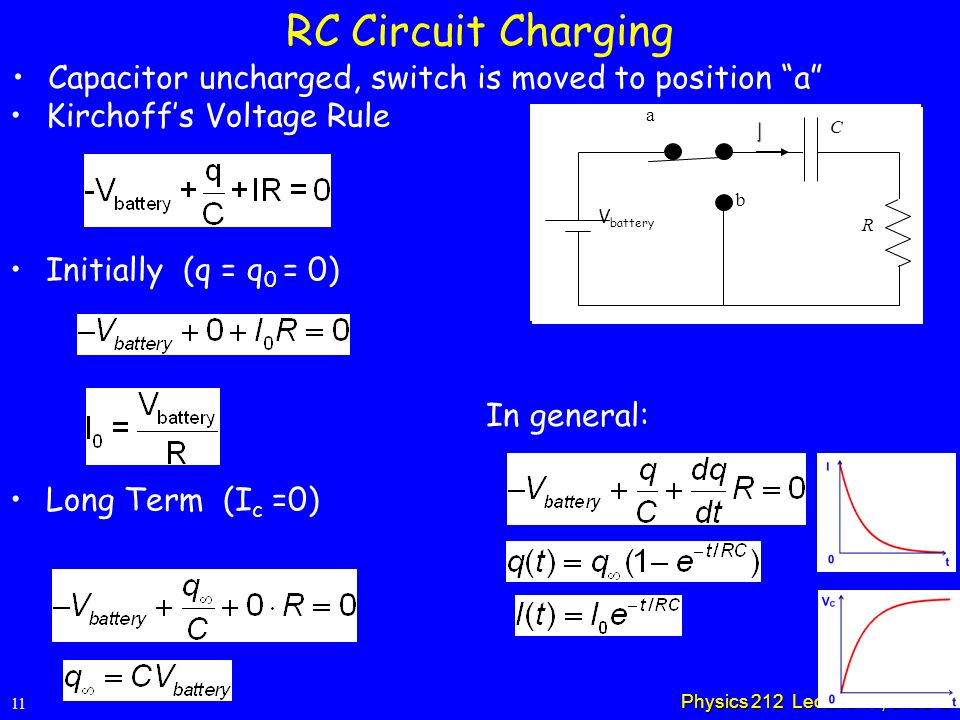
Physics 212 Lecture 11 Rc Circuits Change In Schedule Ppt Video Online Download

Dip Lssm12 P Q T R Table Patch Toggle Switch 3 Pin 2 Gear Sliding Side Dial Switches Aliexpress

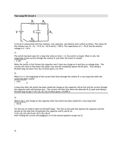
A Circuit Is Constructed With Four Resistors One Capacitor One Battery And A Switch As Shown T Homeworklib

From The Rumor Mill Nintendo Working On A Vr Unit For Switch
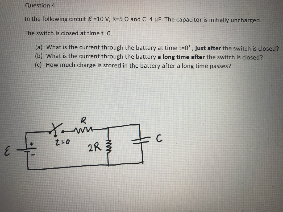
Answered In The Following Circuit E 10 V R 5 Q Bartleby
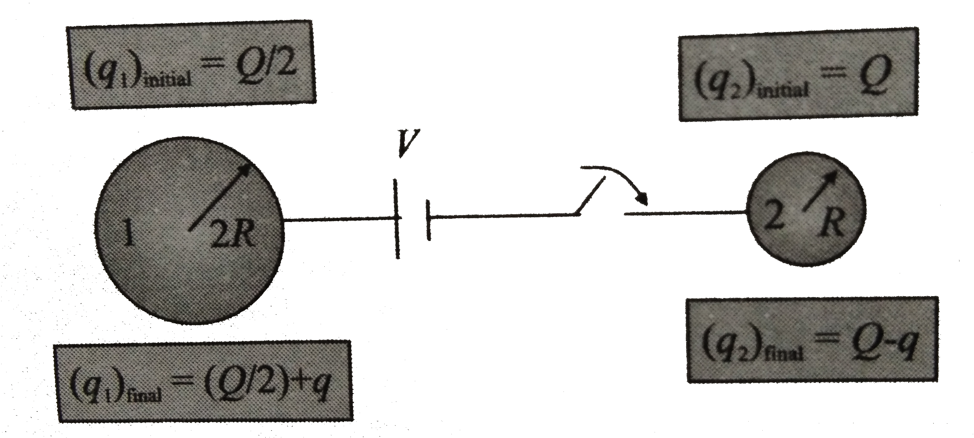
There Are Two Spheres Of Radii R And 2r Having Charges Q And Q 2


